Re: [Simmons Drums] SDS7 – Bus-b oard float mounting
2016-05-02 by Hans
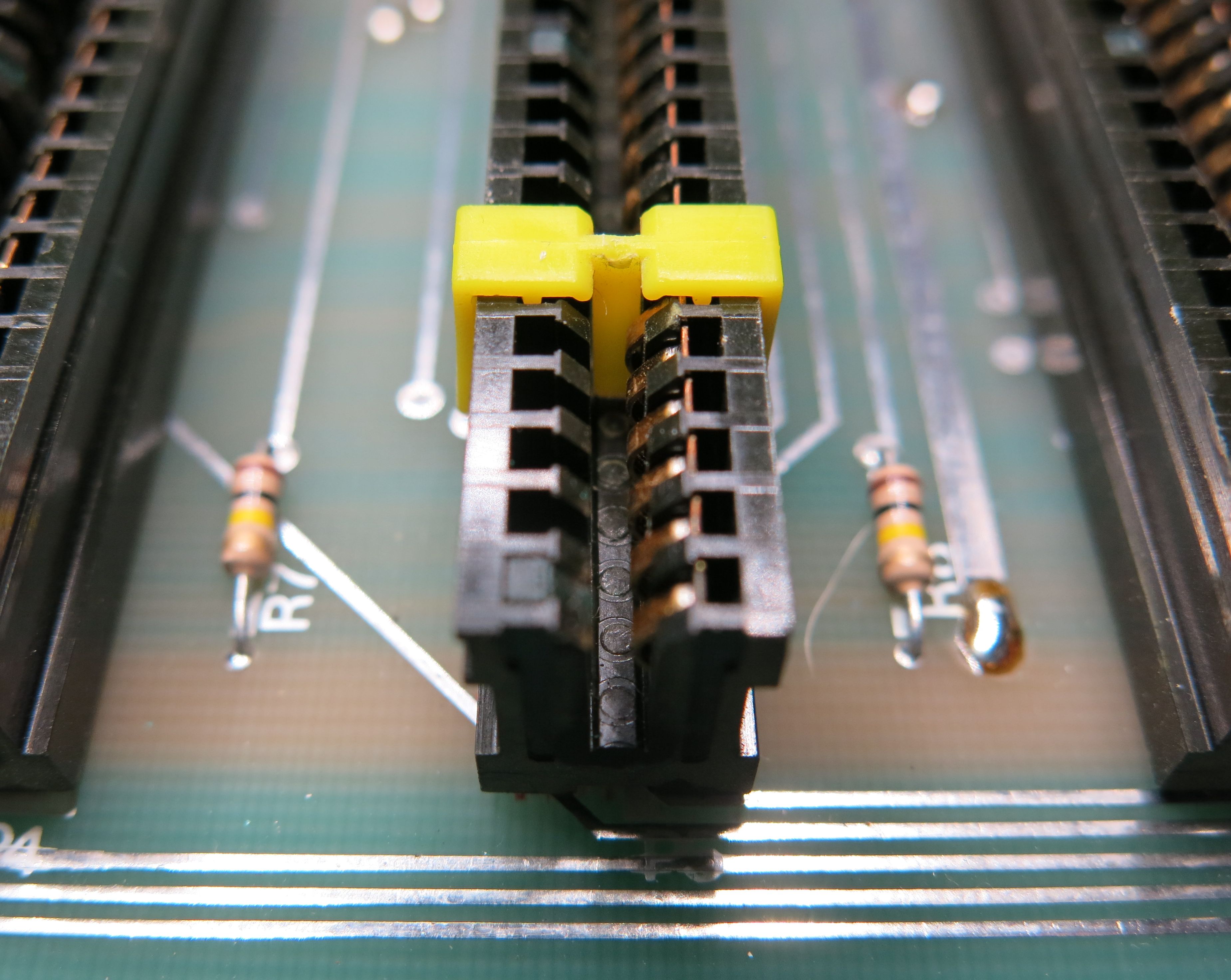
Michael. how do you cut those plastic bits to hold the card in place? I thought I was the next MacGyver when I discovered I had some strips on my work bench that fitted snug with a few stroke on my file. But they came out first time I pulled the card. Looking on how to glue them in I found this photo invaluable to understand how the original key actually hold the card in place.
http://snw.lonningdal.no/sds7/sds7_key_1.jpg
It’s only those four nudges in front that holds the key in its position together with the hooks around the connector. I thought the long tongue going into the edge connector where sliding in a slot. But it isn’t. Actually the tongue doesn’t have a purpose other than to help guiding when the key is installed. Under pressure from top it will push down and rest on the connector pin which by design are not to be trusted to hold its position when a card is inserted.
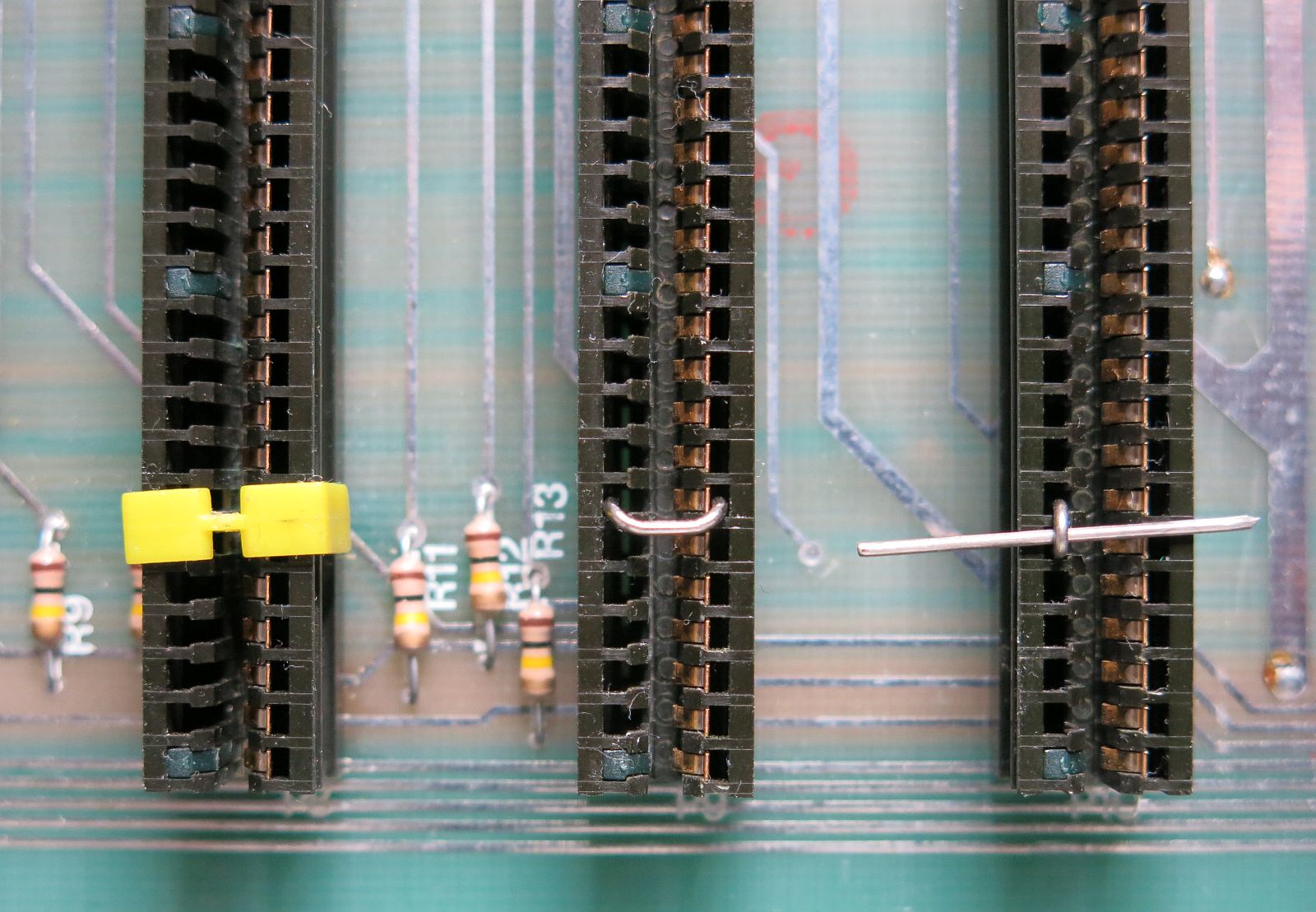
Here is an image of my latest brain storm. After seeing how the nudges in the yellow key take up space behind the connector pin I cut and bent a paper clips so it ‘sag’ down between two connector pins. Here I can probably fill the left side (the side without connector pins) with glue. Of course I will have to address the conductivity issue using a insolated string rather than the paper clip.
This idea might work out better with more umfh and stability if I use a long strait rod running along all 12 slots with loops around the rod glued into two pin-slots on each edge connector and thereby automatic centering the long rod between two connector pins as intended. http://snw.lonningdal.no/sds7/sds7_paper-clip2.jpg
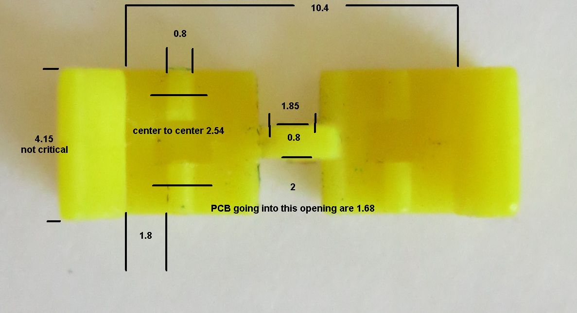
Simon, those parts you have done looks great. As it turns out a friend of a friend do own an early 3D printer. Hardly ever used he can inform us, exactly because of missing cad files. Will you be willing to give it a try if I post links to photos with my caliper strategic placed inside the part in question?
As I already mention, my experience with 3D printing is minimal and those few bits I’ve seen where very brittle. Here we will need something able to flex enough for the hooks to slide over the edge connector, approx 1.5mm stretch for 10mm length. Do you think that will impose a challenge for us?
Thanks for your interest and inputs!
Hans