CGS drum simulator panels
2003-10-25 by Larry Hendry
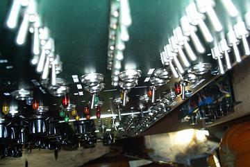
I just finished building (and them significantly modifying) my CGS
drum simulators. I built a 3 tone model behind a 1U Stooge panel.
I have been looking at the panels here in the group and wonder if
anyone has actually ever built one on these panel designs. I say
this because the two I see bring out the RES control which is
normally a trimmer on the board. My expereince is that this control
has only a very small sweet spot and a front panel control would be
touchy to useless unless one used a small pot in series with a
resistor on each side once the known point was found.
Also, I did not see a panel where anyone is attempting the "tune"
modification. After implementing this, I have a whole new concept of
how I would build my next CGS drum simulator package.
And finally, on my drum simulators the Lumex LEDs would hardly light
up at all. I installed a modification that consists of one resistor
and one common NPN transistor (about any will do) that fires the LED.
Since I see drum sim panels, I woudl be interested in hearing from
others than have built theirs.
Larry Hendry