PSIM replacement
2007-04-24 by Larry T.
I'm glad that I've brought a little life to this list, it shows that
there are people like me that wanted a PSIM and will probably never
get one, at least not from Brice.
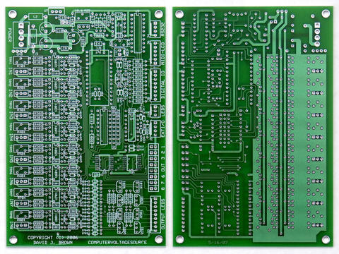
If I may be so bold as to suggest that we have a reference design in
the form of the PSIM itself. 4 analog inputs, 4 analog outputs, 6
LEDs, Run/Stop/Reset inputs/switches, and RS-232. With the addition
of I2C planned expansion to the board itself, we have a usable, and
VERY expandable module. Were there any other I/O 'paths' that were
included with the MPU in this design (I don't remember all of the
discussions we've had over the last year)? The greatest expansion for
this module would be off-board via the I/O paths allowing for an
unlimited number of options and modules to be developed.
I personally want to build the module for use with 1/4" jacks in
either DotCom or MOTM format. I would eventually end up building all
of Dave's add-ons, but with the I2C, I could build as many modules as
I wanted, and locate then anywhere it was convenient within my synth
layout.
The one advantage of Brice's PSIM was that it did get built and some
people got one. Therein lies the biggest drawback to this group, the
'design by committee' has never ended and while there have been a lot
of really good ideas, the complexity of the reference design has
stopped the module from actually becoming a reality.
Dave, could you design a PSIM-like base unit, usable for some CV I/O
but certainly not what add-ons could make? Then as add-ons are
developed, we can pick and choose? If there was a tested PCBExpress
(or other board maker design) I'd buy three (or whatever the minimum
was) and either keep them or sell the extras.
Please, we are actually so close at this point...
Larry T.
there are people like me that wanted a PSIM and will probably never
get one, at least not from Brice.
If I may be so bold as to suggest that we have a reference design in
the form of the PSIM itself. 4 analog inputs, 4 analog outputs, 6
LEDs, Run/Stop/Reset inputs/switches, and RS-232. With the addition
of I2C planned expansion to the board itself, we have a usable, and
VERY expandable module. Were there any other I/O 'paths' that were
included with the MPU in this design (I don't remember all of the
discussions we've had over the last year)? The greatest expansion for
this module would be off-board via the I/O paths allowing for an
unlimited number of options and modules to be developed.
I personally want to build the module for use with 1/4" jacks in
either DotCom or MOTM format. I would eventually end up building all
of Dave's add-ons, but with the I2C, I could build as many modules as
I wanted, and locate then anywhere it was convenient within my synth
layout.
The one advantage of Brice's PSIM was that it did get built and some
people got one. Therein lies the biggest drawback to this group, the
'design by committee' has never ended and while there have been a lot
of really good ideas, the complexity of the reference design has
stopped the module from actually becoming a reality.
Dave, could you design a PSIM-like base unit, usable for some CV I/O
but certainly not what add-ons could make? Then as add-ons are
developed, we can pick and choose? If there was a tested PCBExpress
(or other board maker design) I'd buy three (or whatever the minimum
was) and either keep them or sell the extras.
Please, we are actually so close at this point...
Larry T.