ComputerVoltageSources group photo

Yahoo Groups archive

ComputerVoltageSources

Archive for ComputerVoltageSources.

Index last updated: 2026-03-30 01:00 UTC

Thread

PSIM replacement status?

PSIM replacement status?

2007-04-21 by Larry T.

Hi Everyone

With all of the great work Dave has been doing lately, I have one VERY
pressing question:

WHAT IS THE STATUS OF THE PSIM REPLACEMENT THAT WAS BEING DEVELOPED HERE?

I'd very much like to build one, but there is no chance in h... if
getting an actual PSIM, so the only option is the board that was being
developed here. What happened to that development? Is someone
breadboarding a test version? Will there ever be a PCB for sale? Or
even a known working PCB that we can get the files for in order to
have them made?

Please, I have no design skills and I am dependent on those that do.
Once the designs are done, I can order boards and parts and build the
thing with no problem.

Larry T.

Re: PSIM replacement status?

2007-04-23 by Grant Richter

It is kind of up in the air right now.

Dave has done all the work, and the final disposition of the PCB files is totally up to him.

The project involves completely voluntary work by highly trained people whose time is
valuable.

There is a fear that people will demand support if a PCB is made available, and no here one
is in a position to provide that support.

--- In ComputerVoltageSources@yahoogroups.com, "Larry T." <larry@...> wrote:
>
> Hi Everyone
>
> With all of the great work Dave has been doing lately, I have one VERY
> pressing question:
>
> WHAT IS THE STATUS OF THE PSIM REPLACEMENT THAT WAS BEING DEVELOPED HERE?
>
> I'd very much like to build one, but there is no chance in h... if
> getting an actual PSIM, so the only option is the board that was being
> developed here. What happened to that development? Is someone
> breadboarding a test version? Will there ever be a PCB for sale? Or
> even a known working PCB that we can get the files for in order to
> have them made?
>
> Please, I have no design skills and I am dependent on those that do.
> Once the designs are done, I can order boards and parts and build the
> thing with no problem.
>
> Larry T.
>

Re: PSIM replacement status?

2007-04-23 by djbrow54

My $0.02 on the subject ...

I just picked a feature set that appealed to me and designed it using
a lot of work that others had done. I don't have professional layout
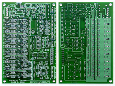
tools and so I just did a prototype using ExpressPCB. The issue is
that quicks are not very affordable. I paid $120 for two boards
without solder mask. 10 mil runs and spacing without solder mask is
not fun to build. The setup fee for solder mask is ~$220. That's
why I haven't posted the PCB files. I did post the schematics and I
have continued to post modifications.

I've been soldering for over 40 years (boy I'm getting old!). I ended
up using head magnifiers along with a hand loupe looking for shorts. I
had three on my board that took me a while to find (and took out
several parts). There are over 50 wires connecting to the board so you
don't just turn it over and look on the back side. In addition, my
board format is too small; I used a 4" x 6" board size. I couldn't get
the MIDI components on (although John put the MIDI circuitry on the
LCD support PCB - thanks!) and my recent modifications do not fit. I
had to go to 1/8W resistors to get the I2C protection to fit and the
input filter capacitors have to be piggybacked on the feedback
resistors. I was hoping that someone with PCB skills and tools would
volunteer to layout a larger PCB with gerber output so the boards
could be more affordable.

In retrospect, I would change my design. The 0 to 10 and +/- 5 volt
input selection is great. I might eliminate the extra 8
potentiometers and just have done this selection with switches. I
wanted the extra potentiometers for a sequencer which I would do now
using I2C.

The 8 output leds are either on or off - there isn't much dynamic
range. I probably should have used a 2x40 or 4x16 display instead of
a 2x16 and just reserved 8 character positions for output indicators.
I have written code to display vertical bars on the LCD that work fine
(although I am not volunteering to do so now!). It would have taken a
larger AVR for the LCD Support design, though. Even with 32 characters
I had to abbreviate a lot of the MIDI patch names to get them to fit
for my sequencer.

Someone suggested a more modular design. I think this is a good idea.
My input filters to reduce noise limit the imput frequency of the
analog inputs. While not a problem due to the limited processing
speed of the AtomPro, I have to wait 7 mS when reading each bank of 8
potentiomenters to let the filters settle. It would have been cheaper
to eliminate the switching reference supplies and just use them to
normalize the inputs. The I2C expansion is a less expensive way to
add 8 additional potentiometers (and faster since I don't have to wait
for the input filters!).

I could see a design using 4 modular boards:
1. Processor with 8 input / output and voltage references
2. Connector / potentiometer interconnect to minimize panel wiring
3. LCD Support for display and MIDI
4. I2C expansion for additional analog and digital inputs

All this group needs is to arrive at a consensus of features and
someone to do the PCB layout. I personally don't feel like there is
enough interest to arrive at a common feature set so whoever does the
layout would get to choose the features.

I have always been open to sharing the PCB design files for those that
are up to the challenge. So far very few have asked. It's also a very
expensive module. Price out 16 potentiometers ($3-$8 ea), knobs ($1-
$2 ea), PCB ($60-$120 for quicks), LCD ($18), processor ($60) and
front panel ($100) and you are already over $300 without any of the
remaining parts. I put a parts list with pricing (probably now out of
date) so you can get a feel for the parts and cost in the files
folder.

However, a bare minimum system is also very useful. 8 resistors and 16
diodes provide 8 uncalibrated analog inputs (correct it in software -
this processor does have floating point). Add to that a LCD and
MIDI and you can have a lot of fun. Maybe this group needs to do a
very basic processor module to get started.

It's all up to this group and the volunteers who move it forward. And
remember, a common set of features means common software and that's
the real plus.

Dave


--- In ComputerVoltageSources@yahoogroups.com, "Grant Richter"
<grichter@...> wrote:
>
> It is kind of up in the air right now.
>
> Dave has done all the work, and the final disposition of the PCB
> files is totally up to him.
>
> The project involves completely voluntary work by highly trained
> people whose time is valuable.
>
> There is a fear that people will demand support if a PCB is made
> available, and no here one is in a position to provide that support.

Re: PSIM replacement status?

2007-04-23 by wiardmodular

> In retrospect, I would change my design. The 0 to 10 and +/- 5 volt
> input selection is great. I might eliminate the extra 8
> potentiometers and just have done this selection with switches. I
> wanted the extra potentiometers for a sequencer which I would do now
> using I2C.

Why would you use the I2C instead of the 8 0 to 10v and 8 offset pots
for a 16 step sequencer? Your original approach seemed quite elegant.

Wasn't the first approach faster for response times? Is the lag
between turning the pots and the output using I2C noticeable/greater
than the 0 to 10 +/-5v pots?

Just curious what the drawbacks were to the first approach.

Re: PSIM replacement status?

2007-04-24 by djbrow54

OK. I take this back. At lunch I spent some time thinking about this
project. The switched reference supplies only take a single DG333A
part. Everything else is still necessary for a +10 volt reference and
a +5 volt offset. Using I2C for an additional 8 inputs would take two
PCF8591 parts so the switched reference supplies is less parts and
cost. I guess it was an elegant approach.

I wanted to minimize input noise so I selected a low pass rolloff of
about 150 Hz. This is certainly higher than the processor can input
data in any meaningful fashion. This adds a slew rate for any step
function, such as switching the reference supplies. The only drawback
is that it takes about 7 mS for the input signals to stabilize after
changing references. In my sequencer application I just simply had to
add two 7 mS delays when switching from one bank of potentiometers to
the other.

I probably could have tried a variety of rolloff frequencies to get
the maximum bandwidth before noise increased. However, it is so hard
to add parts with all the wires that I just settled on one part value.
If I had this on a bench and operational I could play with various
values to minimize the slew rate without increasing noise.

Anyway, back to my lunch exercise. The LCD_Support PCB has a power
voltage regulator, MIDI, and display functionality. This board is
available from John Loffink. My I2C Analog-Digital PCB is available
from ExpressPCB for $20 if you have two friends to buy the extra PCBs.
My sequencer is a program that might be useful to others, especially
as a starting program. So with that in mind, I penciled out a minimum
AtomPro design configuration.

CV outputs adds cost and complexity and takes parts that are in
allocation until late summer. I assume most people have a MIDI to CV
converter of some kind in order to use a typical keyboard. If you
eliminate the CV outputs and run everything off a single supply you
can eliminate a number of parts and still run a useful program like
the sequencer.

Inputs would be:
1 user control potentiometer
3 user switches (start, stop and reset)
Clock input jack
+5 volts in (from LCD Support PCB)
16 sequencer potentiometers/inputs (from I2C Analog-Digial PCB)

Outputs would be:
MIDI (from LCD Support PCB)
Trigger jack
Gate 1 jack
Gate 2 jack

This configuration would have the same features as my PSIM Sequencer
only without the CV output. The program would run unmodified except
for one output routine which would be very simple to modify.

Later, multiple DACs could be added by wiring them to the Trigger /
Gate 1 / Gate 2 outputs and using chip selects from the I2C Analog-
Digital PCB.

This design would be a low-cost minimum system with a useable
sequencer application. A lot of other applications could be run using
MIDI input, output and the switches and controls. Later analog inputs
or analog outputs could be added along with another voltage regulator.

The design is simple enough. My parts count is 8 diodes, 7 resistors,
2 capacitors, 3 switches, 4 IO jacks, 1 AtomPro, and 1 RS-232
connector. Anyone could lay this out as a first-time project using
ExpressPCB for their mini-board service (3 quicks for $51). I'd
supply the schematics and program modifications.

Any interest?

Dave


--- In ComputerVoltageSources@yahoogroups.com, "wiardmodular"
<wiardmodular@...> wrote:
> > In retrospect, I would change my design. The 0 to 10 and +/- 5
> > volt input selection is great. I might eliminate the extra 8
> > potentiometers and just have done this selection with switches. I
> > wanted the extra potentiometers for a sequencer which I would do
> > now using I2C.
>
> Why would you use the I2C instead of the 8 0 to 10v and 8 offset
> pots for a 16 step sequencer? Your original approach seemed quite
> elegant.
>
> Wasn't the first approach faster for response times? Is the lag
> between turning the pots and the output using I2C noticeable/greater
> than the 0 to 10 +/-5v pots?
>
> Just curious what the drawbacks were to the first approach.

Re: PSIM replacement status?

2007-07-22 by Grant Richter

You can see the finished layout at:

http://launch.ph.groups.yahoo.com/group/ComputerVoltageSources/photos/view/26aa?
b=6

--- In ComputerVoltageSources@yahoogroups.com, "Larry T." <larry@...> wrote:
>
> Hi Everyone
>
> With all of the great work Dave has been doing lately, I have one VERY
> pressing question:
>
> WHAT IS THE STATUS OF THE PSIM REPLACEMENT THAT WAS BEING DEVELOPED HERE?
>
> I'd very much like to build one, but there is no chance in h... if
> getting an actual PSIM, so the only option is the board that was being
> developed here. What happened to that development? Is someone
> breadboarding a test version? Will there ever be a PCB for sale? Or
> even a known working PCB that we can get the files for in order to
> have them made?
>
> Please, I have no design skills and I am dependent on those that do.
> Once the designs are done, I can order boards and parts and build the
> thing with no problem.
>
> Larry T.
>

Re: PSIM replacement status?

2007-07-23 by Larry T.

Hmmmm.....

I see SMD! Time to find some SMD tips for my Edsyn 951SX soldering
station! I can't wait for a board! Now if I just had the funds to do
a massive parts buy so I could get started right away!

Larry T.

p.s. THANKS DAVE!!!!!!!!!!!!!!!!!!!!!

--- In ComputerVoltageSources@yahoogroups.com, "Grant Richter"
<grichter@...> wrote:
>
> You can see the finished layout at:
>
>
http://launch.ph.groups.yahoo.com/group/ComputerVoltageSources/photos/view/26aa?
> b=6
>
> --- In ComputerVoltageSources@yahoogroups.com, "Larry T." <larry@>
wrote:
> >
> > Hi Everyone
> >
> > With all of the great work Dave has been doing lately, I have one VERY
> > pressing question:
> >
> > WHAT IS THE STATUS OF THE PSIM REPLACEMENT THAT WAS BEING
DEVELOPED HERE?
> >
> > I'd very much like to build one, but there is no chance in h... if
> > getting an actual PSIM, so the only option is the board that was being
> > developed here. What happened to that development? Is someone
> > breadboarding a test version? Will there ever be a PCB for sale? Or
> > even a known working PCB that we can get the files for in order to
> > have them made?
> >
> > Please, I have no design skills and I am dependent on those that do.
> > Once the designs are done, I can order boards and parts and build the
> > thing with no problem.
> >
> > Larry T.
> >
>

Re: PSIM replacement status?

2007-07-24 by djbrow54

Yes, two parts are SMT. The DAC8420FPZ from Digikey in a DIP16
package is $38.64. The TI parts in SMT are less than half that cost
and better specs. The Analog Devices AD5726YRWZ is about half the
cost of the TI parts with nearly the same specs so there is a
considerable cost delta between the Analog Devices SMT and the DAC8420
DIP part. I haven't yet been able to find the Analog Devices part
through common distribution yet.

If someone were to relay out the board, they could include the DIP
parts for flexibility but the SMT part isn't that hard to solder. It
is 0.05 inch pitch, so only half that of a DIP part.

I just use my Weller soldering iron with a fine tip and small solder.
I use a bit of masking tape to hold the part roughly in place and
solder opposite corners. I remove the tape, then reflow each corner
to better alighn the part. Once it is aligned, it's pretty easy with
a set of magnifying headset to solder each pin. If you bridge, solder
wick will easily remove the excess. It's pretty easy.

Dave


--- In ComputerVoltageSources@yahoogroups.com, "Larry T." <larry@...>
wrote:
>
> Hmmmm.....
>
> I see SMD! Time to find some SMD tips for my Edsyn 951SX soldering
> station! I can't wait for a board! Now if I just had the funds to
do
> a massive parts buy so I could get started right away!
>
> Larry T.
>
> p.s. THANKS DAVE!!!!!!!!!!!!!!!!!!!!!
>
> --- In ComputerVoltageSources@yahoogroups.com, "Grant Richter"
> <grichter@> wrote:
> >
> > You can see the finished layout at:
> >
> >
> http://launch.ph.groups.yahoo.com/group/ComputerVoltageSources/
photos/view/26aa?
> > b=6
> >
> > --- In ComputerVoltageSources@yahoogroups.com, "Larry T." <larry@>
> wrote:
> > >
> > > Hi Everyone
> > >
> > > With all of the great work Dave has been doing lately, I have
one VERY
> > > pressing question:
> > >
> > > WHAT IS THE STATUS OF THE PSIM REPLACEMENT THAT WAS BEING
> DEVELOPED HERE?
> > >
> > > I'd very much like to build one, but there is no chance in h...
if
> > > getting an actual PSIM, so the only option is the board that was
being
> > > developed here. What happened to that development? Is someone
> > > breadboarding a test version? Will there ever be a PCB for
sale? Or
> > > even a known working PCB that we can get the files for in order
to
> > > have them made?
> > >
> > > Please, I have no design skills and I am dependent on those that
do.
> > > Once the designs are done, I can order boards and parts and
build the
> > > thing with no problem.
> > >
> > > Larry T.
> > >
> >
>