ComputerVoltageSources group photo

Yahoo Groups archive

ComputerVoltageSources

Archive for ComputerVoltageSources.

Index last updated: 2026-03-30 01:00 UTC

Thread

PCB layout

PCB layout

2006-03-12 by john mahoney

> Look... if you want to be totally silly, take it to
> synth-diy :^P
>
> H^) harry

Heh... yeah, Synth-DIY is fairly tolerant of sillyness.

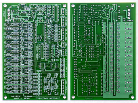
Speaking of SDIY, Harry, are you still willing to do the PCB layout for the
Computer[ized] Voltage Source module? I wouldn't normally "call you out" in
public, but I've mentioned here that you had volunteered for the job (over
on the SDIY list). You should now have a better idea of the plan, so perhaps
you want to reassess your decision.

(In other words, "Bow out while you still can!" Just kidding -- I hope that
you're still up for it, if need be.)
--
john

Re: [ComputerVoltageSources] PCB layout

2006-03-12 by harrybissell

I'm getting up to speed on the concept. The PCB
should be no problem for me. We just need to agree
on a hardware design, and a basic board size.

I'm sure not everyone will be pleased, some will insist
that it have some different size / shape / connectors etc..

But... too bad. I'll make as many happy as I can

I think... no Nixies :^P

no Numatrons, either...

Probably, no tubes at all...

H^) harry

john mahoney wrote:
>
> > Look... if you want to be totally silly, take it to
> > synth-diy :^P
> >
> > H^) harry
>
> Heh... yeah, Synth-DIY is fairly tolerant of sillyness.
>
> Speaking of SDIY, Harry, are you still willing to do the PCB layout
> for the
> Computer[ized] Voltage Source module? I wouldn't normally "call you
> out" in
> public, but I've mentioned here that you had volunteered for the job
> (over
> on the SDIY list). You should now have a better idea of the plan, so
> perhaps
> you want to reassess your decision.
>
> (In other words, "Bow out while you still can!" Just kidding -- I hope
> that
> you're still up for it, if need be.)
> --
> john
>
> SPONSORED LINKS
>
> Music instrument stores Electronic Instruments
>
> Module
>
> ----------------------------------------------------------------------
> YAHOO! GROUPS LINKS
>
> + Visit your group "ComputerVoltageSources" on the web.
>
> + To unsubscribe from this group, send an email to:
> ComputerVoltageSources-unsubscribe@yahoogroups.com
>
> + Your use of Yahoo! Groups is subject to the Yahoo! Terms of
> Service.
>
> ----------------------------------------------------------------------

Re: [ComputerVoltageSources] PCB layout

2006-03-12 by john mahoney

----- Original Message -----
From: "harrybissell"
>
> I'm getting up to speed on the concept.

Sure thing. Good to see you here, in any case.


> The PCB should be no problem for me.

Awesome!


> We just need to agree
> on a hardware design, and a basic board size.

Yep.


> I'm sure not everyone will be pleased, some will insist
> that it have some different size / shape / connectors etc..

Yep, again. But I'm sure we'll reach consensus. (Meaning consensus of the
people doing the real work. LOL! Which doesn't necessarily include me,
yet -- I'm not sure where/how I can be useful.)


> But... too bad....

That's our Harry! ;-)


> I'll make as many happy as I can

What the...? Are you becoming an old softie?! ;-P


> I think... no Nixies :^P
> no Numatrons, either...
> Probably, no tubes at all...

Heh... I'm pretty sure that we've got consensus on that. Actually, it
appears (no pun intended) that the display will require nothing more than a
2-pin interface on the main board. So, people will be free to design Nixie
displays if they really want to. (I *think* it was a joke... though I love
Nixies, too.)
--
john <--(Still wondering why the Flamenco music at the tapas restaurant had
to be so loud that my ears are ringing. Ugh!)

Re: PCB layout

2006-03-12 by djbrow54

Two comments. First, I'd go with a 4 pin interface. I think there
should be a ground and it would be nice to tie the resets together.
You can do them independent but you have timing issues on power-up not
knowing which processor is active first (although the displays take
some time to initialize.

On the subject of Nixies ... my other hobby is vintage radio, from the
late teens until about 1940. While I still have a stash of Nixies,
you really want tuning eye tubes on each of the CV outputs. The
1629 versions are still pretty plentiful as military NOS. It's also
easier to punch the round holes for them in the panel. You think I'm
kidding, don't you ...

http://www.radioremembered.org/tuneye.htm

Dave

> ----- Original Message -----
> Actually, it appears (no pun intended) that the display will
> require nothing more than a 2-pin interface on the main board
> So, people will be free to design Nixie displays if they really
> want to. (I *think* it was a joke... though I love
> Nixies, too.)

Re: [ComputerVoltageSources] Re: PCB layout

2006-03-12 by john mahoney

----- Original Message -----
From: "djbrow54"
>
> On the subject of Nixies ... my other hobby is vintage radio, from the
> late teens until about 1940. While I still have a stash of Nixies,
> you really want tuning eye tubes on each of the CV outputs. The
> 1629 versions are still pretty plentiful as military NOS. It's also
> easier to punch the round holes for them in the panel. You think I'm
> kidding, don't you ...

No kidding, that would look amazing! (Power consumption be damned. Think of
them as VCO heaters! ;-)
--
john

LCD display and Magic Eye Tubes

2006-03-12 by Grant Richter

RE: LCD display

4 pins would be Ground, TXD, Reset amd +5 volts, is that correct?
The voltage regulator is only a TO-92, don't plan on powering the LCD if it draws more
than 25 ma.

RE: Magic Eye Tubes

OK, this time around I am going to buffer the DAC reference with an op-amp. I'll put a
copper pad on the reference op-amp output.

If you use the buffered reference pad as ground, then the DACs will go from zero to -10
volts relative. That will support the Magic Eye Tubes with a zero to -8 volt control range.

The 250 volt B+ supply is your problem. My only request is that you publish a picture of
the finished display (if you do this crazy thing).

--- In ComputerVoltageSources@yahoogroups.com, "djbrow54" <davebr@...> wrote:
>
> Two comments. First, I'd go with a 4 pin interface. I think there
> should be a ground and it would be nice to tie the resets together.
> You can do them independent but you have timing issues on power-up not
> knowing which processor is active first (although the displays take
> some time to initialize.
>
> On the subject of Nixies ... my other hobby is vintage radio, from the
> late teens until about 1940. While I still have a stash of Nixies,
> you really want tuning eye tubes on each of the CV outputs. The
> 1629 versions are still pretty plentiful as military NOS. It's also
> easier to punch the round holes for them in the panel. You think I'm
> kidding, don't you ...
>
> http://www.radioremembered.org/tuneye.htm
>
> Dave
>
> > ----- Original Message -----
> > Actually, it appears (no pun intended) that the display will
> > require nothing more than a 2-pin interface on the main board
> > So, people will be free to design Nixie displays if they really
> > want to. (I *think* it was a joke... though I love
> > Nixies, too.)
>