Overview
Korg Poly800/EX800 Users
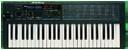
This group is for users and abusers of KORG POLY 800 and EX800 music synthesizers. We have owners and service manuals in the files section and there are sections on modifications. We also discuss the HAWK-800 upgrade kit.
- Members
- 1355
- Created
- 2001-07-26
Search
Search this archive
Thread snapshot
Last 10 threads
- Yahoo groups being shut down (18 messages, 2019-10-30)
- polycheesy mod (1 messages, 2019-10-19)
- EX-800 sysex (14 messages, 2019-10-08)
- Late! install of v1.3 hawkmod in ex800 (24 messages, 2019-09-03)
- EX800 vs Poly800 Eprom differences (21 messages, 2019-08-30)
- EX-800 button restoration (10 messages, 2019-08-29)
- Arpeggiator coming soon! (16 messages, 2019-08-29)
- Synth gear to a good home... (5 messages, 2019-06-02)
- Install issues and possible further queries (29 messages, 2019-04-29)
- Chord mode and MIDI (9 messages, 2019-04-08)