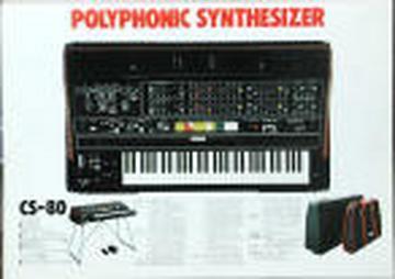
My CS80 photo with stand as promised...
2004-09-15 by Quazimodo
Yahoo Groups archive
Archive for yamahacs80.
Index last updated: 2026-03-30 01:20 UTC
Thread
2004-09-15 by Quazimodo
2004-09-16 by The Old Crow
2004-10-19 by David Rogoff
2004-10-20 by STEPHEN TELLER
On Oct 20, 2004, at 10:17 AM, yamahacs80@yahoogroups.com wrote:
> Subject: Re: Another CS-80 on the overhaul bench
>
>
> Hi all.
>
> I'm getting into refurbishing/fixing my CS-80 and thought some people
> would be interested in seeing what's involved. I created an album in
> the Photos page called CS80 renovation.
>
> There's a picture labeled "Here's where it's happening!", which shows
> a corner of my TV room, converted to a repair shop. I picked up a
> Weller desoldering station and Beckman Oscilloscope very cheap on
> eBay. On the floor, you can see the box from Digikey where I got all
> the CMOS chips, IC sockets, and capacitors.
>
> There are also three pics of the TSB boards. These are the first I'm
> upgrading. They multiplex the aftertouch voltages from the keyboard.
> I desoldered the five 4051 chips and installed machined sockets. One
> semi-problem: the holes between the rows of pins are supposed to be
> exactly 0.3" apart. Well, they're slightly wider. This isn't a
> problem with the chips, since the leads are flexible. However, it
> made putting in the sockets a pain. Also, since the socket pins were
> forces into a slight angle, it made getting the new 4051s in
> difficult. For the last few, I cut the sockets in half and inserted
> each row separately. This made everything much easier.
>
> In the pic "Back of upgraded TSB board", you can see the little bypass
> caps I put on the 4051s. The 4051s are different than most digital
> CMOS parts since they're analog switches. They have a negative supply
> (-6.5v), and two positive supplies, one for digital and one for
> analog. They are both tied to +8.5v. The minimal bypassing was
> between these two supplies. I added caps from each to ground. The
> ones that reached a longer distance are covered in red heat-shrink
> tubing.
>
> In pic "TSB board after upgrade" you can see the 4051s in their
> sockets. In the top, left corner you can also see two bigger, blue
> capacitors I added to bypass the +8.5 and -6.5 supplied where they
> enter the board (the red and green wires in the corners).
>
> One last weird thing: the two TSB boards in my CS80 are slightly
> different versions! I think they're electronically identical, but the
> PC boards are a bit different. After I put the caps on the first
> board I was just going to put them in the same places on the second
> board. When I tried to do that, I couldn't find some of the reference
> points I was looking for. I thought I was going blind, but then
> realized the differences.
>
> The good part is that everything still works after all the soldering
> (which is really good since it was all working before I started)!
>
> Now I'm on to the other boards.
>
> David
>
2004-10-23 by David Rogoff
2004-10-24 by The Old Crow
On Sat, 23 Oct 2004, David Rogoff wrote:
> Update:
>
> I finished the first of two KBC boards. A bunch of pictures are in
> Photos -> CS80 Renovation -> KBC. The caps on the back of each IC go
> between VDD and VSS. The strange thing is that usually VSS is
> 0v/ground and VDD is anywhere from +5v to +18 for CMOS. However,
> since the CMOS digital chips are also being used to swtich analog
> control voltages, Yamaha uses +8.5v for VDD and -6.5v for VSS.
>
> Therefore, the little bypass caps bypass the two supplies to each
> other, not to ground. On the TSB board I put seperate caps to ground
> from each, but there weren't easily accessible grounds on the KBCs.
2004-10-31 by David Rogoff
2004-11-01 by barbara_Streisand@hotmail.com
----- Original Message -----From: David RogoffSent: Sunday, October 31, 2004 8:15 PMSubject: [yamahacs80] Channel lights - was Re: Another CS-80 on the overhaul bench
New stuff:
I just added some cool lights to my CS-80. When tuning the keyboard,
or for troubleshooting, you need to know which voice card is sounding.
There are eight TRG signals that go from the KAS board (which scans
the keyboard) to the M boards (voice cards). I tried driving LEDs
directly from these, but the load lowered the voltage too much. It
still worked, but I was worried it would be flakey. So, I copied
(with minor value changes) the same transistor drivers (the CMOS parts
used in the keyboard circuits don't have much power to drive anything)
used on the KAS to drive the TRG lines. The results are shown in
Photos -> CS80 Renovation -> lights.
I used tri-color LEDs so that they're green when idle and red when
active. Because there's nothing blocking the light between the LEDs,
an LED glowing red makes the green ones next to it look a bit orange.
Right now the board is just loose, but I might mount it under the
panel, with the LEDs to the left of the ribbon. I've also thought of
adding some LEDs for the PWM rates, the ring mod rate, and the LFO rate.
One more thing: the CS-80 service manual came with great, huge,
fold-out schematics and block diagrams for the whole unit. There are
very good scans of these on synthfool at
http://www.synthfool.com/schematics/cs80_1.jpg and
http://www.synthfool.com/schematics/cs80_2.jpg. I tried printing
these out in parts and taping them together, but it was a big pain and
didn't line up. Last week I just popped the files on a CDR, went to
Kinkos, and had them both printed on their large-format
black-and-white printer. For both of them printed about 3 x 6 feet it
cost $16. Great wall posters and invaluable for tracking down problems!
David
2004-11-05 by David Rogoff
--- In yamahacs80@yahoogroups.com, <barbara_Streisand@h...> wrote:
> Great thanks for the files!!!
> best david
> ----- Original Message -----
> From: David Rogoff
> To: yamahacs80@yahoogroups.com
> Sent: Sunday, October 31, 2004 8:15 PM
> Subject: [yamahacs80] Channel lights - was Re: Another CS-80 on
the overhaul bench
>
>
>
> New stuff:
>
> I just added some cool lights to my CS-80. When tuning the keyboard,
> or for troubleshooting, you need to know which voice card is sounding.
> There are eight TRG signals that go from the KAS board (which scans
> the keyboard) to the M boards (voice cards). I tried driving LEDs
> directly from these, but the load lowered the voltage too much. It
> still worked, but I was worried it would be flakey. So, I copied
> (with minor value changes) the same transistor drivers (the CMOS parts
> used in the keyboard circuits don't have much power to drive anything)
> used on the KAS to drive the TRG lines. The results are shown in
> Photos -> CS80 Renovation -> lights.
>
> I used tri-color LEDs so that they're green when idle and red when
> active. Because there's nothing blocking the light between the LEDs,
> an LED glowing red makes the green ones next to it look a bit orange.
> Right now the board is just loose, but I might mount it under the
> panel, with the LEDs to the left of the ribbon. I've also thought of
> adding some LEDs for the PWM rates, the ring mod rate, and the LFO
rate.
>
> One more thing: the CS-80 service manual came with great, huge,
> fold-out schematics and block diagrams for the whole unit. There are
> very good scans of these on synthfool at
> http://www.synthfool.com/schematics/cs80_1.jpg and
> http://www.synthfool.com/schematics/cs80_2.jpg. I tried printing
> these out in parts and taping them together, but it was a big pain and
> didn't line up. Last week I just popped the files on a CDR, went to
> Kinkos, and had them both printed on their large-format
> black-and-white printer. For both of them printed about 3 x 6 feet it
> cost $16. Great wall posters and invaluable for tracking down
problems!
>
> David
>
>
>
>
> Yahoo! Groups Sponsor
> ADVERTISEMENT
>
>
>
>
>
>
------------------------------------------------------------------------------
> Yahoo! Groups Links
>
> a.. To visit your group on the web, go to:
> http://groups.yahoo.com/group/yamahacs80/
>
> b.. To unsubscribe from this group, send an email to:
> yamahacs80-unsubscribe@yahoogroups.com
>
> c.. Your use of Yahoo! Groups is subject to the Yahoo! Terms of
Service.
2004-11-23 by David Rogoff
2004-11-28 by David Rogoff
--- In yamahacs80@yahoogroups.com, "David Rogoff" <david@t...> wrote:
>
> Latest update (I'd been waiting for some more parts):
>
> Power Supply (pics under Photos > CS80 renovation > Power Supply):
> I replaced all the bypass caps on the power supply circuit board. As
> some of you know (especially if you've read Crow's site), the big
> electrolytic caps dry out after many years and stop doing their job,
> which is to smooth out the voltage.
>
> I used parts with at least the same capacitance value (in general,
> more is better) and voltage value. The catch is that the size of caps
> have changed over the years. It's not just micro-chips that have
> gotten smaller (see pic "caps are smaller now!" to see new/old caps
> next to each other). In fact, the old 5600uF caps had a third lead,
> which wasn't electrically connected, just to support it on the board.
> This made mounting the biggest one a little tricky.
>
> My wife didn't appreciate that the old, lavender-colored caps have
> been replaced by ugly black, grey, and brown ones. Oh well.
>
>
> TKC (pics under Photos > CS80 renovation > TKC):
> This board was 100% old CMOS digital chips with no bypass caps! I
> definitely needed the desoldering station for this one. It's also
> tricky, since there are about 12 types of chips on this board, which
> all look virtually the same. In addition, they all face one way,
> except about four of them! If you look at "Back - after with caps",
> you'll see why Crow was smart to use the sockets with the built-in
> bypass caps.
>
> I think the only board I have left is the KAS. I should have my
> de-soldering station for sale in a couple of weeks!
>
> David