2016-02-08 by Bob Grieb
That's great news.   We can help you a lot more easily if you have a scope.

Probe TP4, pin 32 of the MCU.   Connect the scope probe gnd to TP3 or the big gnd wire,
and clip the tip on the ring at TP4.   Set the triggering to Ch 1.   Adjust the trigger level to
2V and the volts/div to 2 volts, taking into account whether you are using a 10:1 probe.

According to my comment in the code listing, you should see a pulse there every 7 mSec
or so if the CPU is executing the code correctly.

Also, you never said what you see on the RESETb input to the CPU.

It should be sitting high.  If you set the scope to trigger at 2V and probe that pin,
the scope should not trigger, if it's in "manual" trigger mode.  If it triggers, then there
is a glitch on that pin which would not be good.  Then if you switch to "auto" trigger,
you should see a nice >3.5VDC constant level.

Bob
--------------------------------------------
On Mon, 2/8/16, jw_dewdney@yahoo.com [PolySix] <PolySix@yahoogroups.com> wrote:
Show quoted textHide quoted text
 Subject: Re: [PolySix] Re: The Post I didn't want to make....
 To: PolySix@yahoogroups.com
 Date: Monday, February 8, 2016, 12:51 PM


       Hi Bob... actually i realized about five minutes
 after posting that was the thermistor, though i missed it
 because i was working rather slavishly from Jed's
 spreadsheet which didnt seem to have it on
 there.
 i DO have a
 scope actually. a lovely Tek 2445A. however I'm a bit
 intimidated about troubleshooting logic circuits and
 signals....ive only ever used it for analogue audio stuff
 really... so theres more to learn for me.
 And i DID get some more functioning
 5v test points on the board though still not TP1 which is
 zero... and TP2 is a bit low at 4.1v or thereabouts. I am a
 bit confused as the manual uses a totally different language
 like 'TP-J7' and i am not sure how they correspond
 to the board ...


#yiv1538245622 #yiv1538245622 --2016-02-09 by jw_dewdney@yahoo.com
HI Bob - sorry it took me awhile to dig the scope out and find the probes etc.
So - I got it all up and running and damned if i can see a signal ANYWHERE. From both TP4 and from the RESET (pin 4 according to the drawings i found) I get only positive DC offset and no pulses whatsoever. I double checked my with my Tek TX1 dmm - which does a nice job as a frequency counter also - and from TP4 I got 0.004 Hz (meaning zero) pulse activity at plus 4.9v offset... and from the reset pin I get about 0.24mV dc offset (positive). I'm getting positive offsets of betwen 1.5 and 5 volts on nearly every pin on the CPU. TP1 gives me 0.6-ish volts positive - so maybe that's got SOMETHING to do with it? Not sure. Still driving me crazy why that should be... I'm trying to follow the circuit back to the power connector but get a bit lost when i do...
2016-02-09 by Bob Grieb
If reset is at 0.24V relative to ground, then the CPU is being held in reset.
It's an active low input, so it's active.
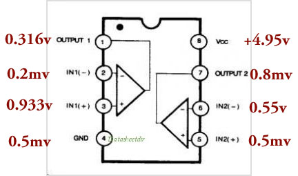
Measure pins 5, 6, and 8 of IC5 please.
Pin 5 should be roughly 1.1 volts DC.
Pin 8 should be 5.0 VDC +/- 0.1 volts
Pin 6 must be less than what you have at pin 5.
Also, make sure you have installed R35, as IC5 can only pull
reset low. The resistor is needed to pull it high when the IC is not
pulling it low. (Google "open collector")
If reset is asserted to the CPU, there is no point to look at any
other CPU pin except the two oscillator pins (with a scope, not the meter)
and the power pins. So 2,3,40, and 20. Check all 4 of these with the scope
and tell us what you see.
But it won't run until you get the reset issue sorted out.
Bob
--------------------------------------------
On Mon, 2/8/16, jw_dewdney@yahoo.com [PolySix] <PolySix@yahoogroups.com> wrote:
Show quoted textHide quoted text
 Subject: [PolySix] Re: The Post I wanted to make....
 To: PolySix@yahoogroups.com
 Date: Monday, February 8, 2016, 11:54 PM


       HI Bob - sorry it took me awhile to dig the scope
 out and find the probes etc.
 So - I got it
 all up and running and damned if i can see a signal
 ANYWHERE. From both TP4 and from the RESET (pin 4 according
 to the drawings i found) I get only positive DC offset and
 no pulses whatsoever. I double checked my with my Tek TX1
 dmm - which does a nice job as a frequency counter also -
 and from TP4 I got 0.004 Hz (meaning zero) pulse activity at
 plus 4.9v offset... and from the reset pin I get about
 0.24mV dc offset (positive). I'm getting positive
 offsets of betwen 1.5 and 5 volts on nearly every pin on the
 CPU. TP1 gives me 0.6-ish volts positive - so maybe
 that's got SOMETHING to do with it? Not sure. Still
 driving me crazy why that should be... I'm trying to
 follow the circuit back to the power connector but get a bit
 lost when i do...


#yiv3082498721 #yiv3082498721 --2016-02-09 by jw_dewdney@yahoo.com
testing
2016-02-09 by jw_dewdney@yahoo.com
curious how when I post from the tablet (ipad) the post happens instantly - whereas posting from the computer (firefox) takes about an HOUR to show up... weird!
here is my result from the LM393 (IC5) - the rest forthcoming
2016-02-09 by jw_dewdney@yahoo.com
I will try swapping out IC5 for another just in case this one is bad... getting totally different readings from IC6 - which is also a LM393.
2016-02-09 by jw_dewdney@yahoo.com
also currently having super annoying scope issues (needs service i guess) with the scope losing signal at vertical scaling below 1v/div and also only able to acquire signals at very low horiz. sweep speeds... nothing like having problems to diagnose and problems with your test equipment at the same time!!
2016-02-09 by jw_dewdney@yahoo.com
so i scoped the pins on the 8048. pin 2 gave me a pretty healthy looking hf sine wave. pin 3 gave me a rather lumpier looking sine at about a thurd the amplitude. pin 20 gave me nothing at all.... no offset ... and pin 40 gave me a healthy dc only offset.
i could hazard a guess at the voltages but channels 1 and 2 on my scope dont agree at all and also dont agree with my dmm when measuring a AA battery... (throws hands up)
2016-02-09 by eidorian@aladan.net
I don't mean to insult you, but if you're new to scopes then you
might not be aware that many have adjustable attenuation controls on X/Y
inputs, via either or both an analogue control or a multi-position
switch. It would be worth checking the scope's user manual for more
information if you haven't already done so. Then again, maybe it is just
poorly calibrated :)

Cheers,
A.

On 2016-02-10 08:45,
jw_dewdney@yahoo.com [PolySix] wrote:

> so i scoped the pins on the
8048. pin 2 gave me a pretty healthy looking hf sine wave. pin 3 gave me
a rather lumpier looking sine at about a thurd the amplitude. pin 20
gave me nothing at all.... no offset ... and pin 40 gave me a healthy dc
only offset.
>
> i could hazard a guess at the voltages but channels 1
and 2 on my scope dont agree at all and also dont agree with my dmm when
measuring a AA battery... (throws hands up)
>


Links:
------
[1]
https://groups.yahoo.com/neo/groups/PolySix/conversations/messages/5017;_ylc=X3oDMTJwNDIxMmpvBF9TAzk3MzU5NzE0BGdycElkAzE5OTQ4OTQEZ3Jwc3BJZAMxNzA3NzA5ODU4BG1zZ0lkAzUwMTcEc2VjA2Z0cgRzbGsDcnBseQRzdGltZQMxNDU1MDU2MTA2?act=reply&messageNum=5017
[2]
https://groups.yahoo.com/neo/groups/PolySix/conversations/newtopic;_ylc=X3oDMTJlZGQ0bG9oBF9TAzk3MzU5NzE0BGdycElkAzE5OTQ4OTQEZ3Jwc3BJZAMxNzA3NzA5ODU4BHNlYwNmdHIEc2xrA250cGMEc3RpbWUDMTQ1NTA1NjEwNg--
[3]
https://groups.yahoo.com/neo/groups/PolySix/conversations/topics/5005;_ylc=X3oDMTM0b29jbmFvBF9TAzk3MzU5NzE0BGdycElkAzE5OTQ4OTQEZ3Jwc3BJZAMxNzA3NzA5ODU4BG1zZ0lkAzUwMTcEc2VjA2Z0cgRzbGsDdnRwYwRzdGltZQMxNDU1MDU2MTA2BHRwY0lkAzUwMDU-
[4]
https://groups.yahoo.com/neo/groups/PolySix/photos/photomatic/687780476;_ylc=X3oDMTE4M3R1OW82BF9TAzk3MzU5NzE0BGNmOQNQSE9UT01BVElDBHNlYwNtZWdhcGhvbmU-
[5]
https://groups.yahoo.com/neo/groups/PolySix/info;_ylc=X3oDMTJlcnBpdTZ2BF9TAzk3MzU5NzE0BGdycElkAzE5OTQ4OTQEZ3Jwc3BJZAMxNzA3NzA5ODU4BHNlYwN2dGwEc2xrA3ZnaHAEc3RpbWUDMTQ1NTA1NjEwNg--
[6]
https://groups.yahoo.com/neo/groups/PolySix/members/all;_ylc=X3oDMTJmcmZkbjNmBF9TAzk3MzU5NzE0BGdycElkAzE5OTQ4OTQEZ3Jwc3BJZAMxNzA3NzA5ODU4BHNlYwN2dGwEc2xrA3ZtYnJzBHN0aW1lAzE0NTUwNTYxMDY-
[7]
https://groups.yahoo.com/neo;_ylc=X3oDMTJkM3Mza2NzBF9TAzk3NDc2NTkwBGdycElkAzE5OTQ4OTQEZ3Jwc3BJZAMxNzA3NzA5ODU4BHNlYwNmdHIEc2xrA2dmcARzdGltZQMxNDU1MDU2MTA2
[8]
https://info.yahoo.com/privacy/us/yahoo/groups/details.html
[9]
https://info.yahoo.com/legal/us/yahoo/utos/terms/
2016-02-09 by jw_dewdney@yahoo.com
fair enough eidorian_aladan... though this scope's adjustment range is only ± 50% max. Everything else was zeroed out - been using scopes for 40 years - but only very sporadically - and not enough to have a high degree of confidence with what i'm doing - and this one is relatively new to me but sort of an ebay 'junker' with other issues as well. But good advice - yes I've been combing over the manual as I've only spent a handful of hours with this thing so far... 'know thy tools'...
2016-02-10 by jw_dewdney@yahoo.com
Bob..? you around? (the above posts were for you)
2016-02-10 by Roman Sowa
Maybe that's just faulty/dirty/corroded range switch on the scope. Try
to turn it like crazy quite a few times so the contatcs should wipe out
a bit and clean.
I also find the probes themselves to cause unbelievable readings by poor
contact inside, and especially when spring clip is attached. And I'm not
talking about toy crap, but genuine Tek probes not older than 10-15 years.

Roman

W dniu 2016-02-10 o 00:55, jw_dewdney@yahoo.com [PolySix] pisze:
Show quoted textHide quoted text
>
>
> fair enough eidorian_aladan... though this scope's adjustment range is
> only � 50% max. Everything else was zeroed out - been using scopes for
> 40 years - but only very sporadically - and not enough to have a high
> degree of confidence with what i'm doing - and this one is relatively
> new to me but sort of an ebay 'junker' with other issues as well. But
> good advice - yes I've been combing over the manual as I've only spent a
> handful of hours with this thing so far... 'know thy tools'...
>
>
2016-02-10 by jw_dewdney@yahoo.com
actually i discovered the probe i was using was bad - not only semi intermittent but it was a 10x probe that didn't trigger the 10x compensation on the scope the way my other one (identical) does - I didn't realize this before. But it was a relief to do so - and I have renewed confidence in the scope now - so that's better.
2016-02-10 by Roman Sowa
I think you should see about 1V at pin 2. Since it's nearly 0, my guess
is that D2 (3.9V zener) is missing or burned out, or there is a short
somewhere around to GND.

Roman

W dniu 2016-02-09 o 21:30, jw_dewdney@yahoo.com [PolySix] pisze:
Show quoted textHide quoted text
> [Attachment(s) <#TopText> from jw_dewdney@yahoo.com [PolySix] included
> below]
>
> curious how when I post from the tablet (ipad) the post happens
> instantly - whereas posting from the computer (firefox) takes about an
> HOUR to show up... weird!
>
> here is my result from the LM393 (IC5) - the rest forthcoming
>
>
2016-02-10 by Bob Grieb
My posts were intended to give you some info that would help you troubleshoot the reset circuit.   Better for you to figure out how this simple circuit works than for us to tell you which part to replace.
As someone suggested, the voltage created by subtracting the zener drop from five volts should be about one volt.  If you don't see that, then it's time to investigate.
Bob
--------------------------------------------
On Tue, 2/9/16, jw_dewdney@yahoo.com [PolySix] <PolySix@yahoogroups.com> wrote:

 Subject: [PolySix] Re: The Post I wanted to make....
 To: PolySix@yahoogroups.com
 Date: Tuesday, February 9, 2016, 8:24 PM

 Bob..? you around? (the
 above posts were for you)
2016-02-10 by Bob Grieb
Some reason you don't want to read voltage and frequency off the screen of your scope?

One pin of the oscillator will look more sinusoidal.  The other will look more like a square wave, but they will vary from one chip to the next.  Sounds like it's oscillating, at least.  Probably the oscillator is fine.
--------------------------------------------
On Tue, 2/9/16, jw_dewdney@yahoo.com [PolySix] <PolySix@yahoogroups.com> wrote:
Show quoted textHide quoted text
 Subject: [PolySix] Re: The Post I wanted to make....
 To: PolySix@yahoogroups.com
 Date: Tuesday, February 9, 2016, 5:15 PM

 so i scoped the pins on
 the 8048. pin 2 gave me a pretty healthy looking hf  sine
 wave. pin 3 gave me a rather lumpier looking sine at about a
 thurd the amplitude. pin 20 gave me nothing at all.... no
 offset ... and  pin 40 gave me a healthy dc only offset.


  i could hazard a guess at
 the voltages but channels 1 and 2 on my scope dont agree at
 all and also dont agree with my dmm when measuring a AA
 battery... (throws hands up)
2016-02-10 by jw_dewdney@yahoo.com
oh Bob you are such a tease! :) no but ... i am deeply grateful for your help. i am in here way over my head... i was hoping that if i did everything 'by the book' that i would be able to get it to work. it doesnt seem like a simple circuit to me... ive never worked on anything with a microprocessor before. when i did my undergrad in physics we just calculated far far simpler LCR circuits etc ... apart from that its just been 'hobbyist' type soldering jobs... but i do not want to be overly dependent on anyone here.... of course i want to encourage people to be helpful and not be a drain on people so i get that. but yeah i think thats the right response... you have to encourage people to learn what they do not understand! and transistors and ICs have always been a real weak spot for me... i feel a bit lost when it comes to such things...
so ill try to take over from here i guess...
incidentally... i remember putting in that zener and wondering how on earth one can distinguish them from 1N4148 diodes... they are identical in almost every way... so i just take it on faith that the zeners i was sent were not mixed up for 1N4148s by the seller! but who knows. my next step is to replace ALL the resistors for ones from another supplier since i checked them for capacitance and they have unusual properties in that regard... (a head scratcher)
2016-02-10 by <backshall1@bellsouth.net>
Don’t go replacing all the resistors because of unusual capacitance readings if you are doing the readings with the resistors soldered to the board. In fact don’t go replacing them at all. That’s a bit like somebody who decides to “recap” their old synth just because the caps are old. Too much room for error and further damage there, when there is nothing likely to be wrong with them. Sometimes it helps to post some hi-res photos of your new board. There are enough people here who have built them that might be able to spot something obvious that you missed.
Don B.
Show quoted textHide quoted text
From: mailto:PolySix@yahoogroups.com
Sent: Wednesday, February 10, 2016 2:31 PM
To: PolySix@yahoogroups.com
Subject: Re: [PolySix] Re: The Post I wanted to make....


oh Bob you are such a tease! :) no but ... i am deeply grateful for your help. i am in here way over my head... i was hoping that if i did everything 'by the book' that i would be able to get it to work. it doesnt seem like a simple circuit to me... ive never worked on anything with a microprocessor before. when i did my undergrad in physics we just calculated far far simpler LCR circuits etc ... apart from that its just been 'hobbyist' type soldering jobs... but i do not want to be overly dependent on anyone here.... of course i want to encourage people to be helpful and not be a drain on people so i get that. but yeah i think thats the right response... you have to encourage people to learn what they do not understand! and transistors and ICs have always been a real weak spot for me... i feel a bit lost when it comes to such things...


so ill try to take over from here i guess...

incidentally... i remember putting in that zener and wondering how on earth one can distinguish them from 1N4148 diodes... they are identical in almost every way... so i just take it on faith that the zeners i was sent were not mixed up for 1N4148s by the seller! but who knows. my next step is to replace ALL the resistors for ones from another supplier since i checked them for capacitance and they have unusual properties in that regard... (a head scratcher)
2016-02-10 by jw_dewdney@yahoo.com
.... because of the aforementioned probe problems - i couldn't trust ANYTHING i was seeing on the screen - turned out one of my two x10 probes wasn't 'talking to' the scope the way it should... though they are identical to my other x10 probe and i've used them interchangeably - so i thought the problem was with the scope. Yes - anyway- thanks for pushing me onto the scope - it's helping some!
2016-02-10 by jw_dewdney@yahoo.com
Yes - i totally agree with that! No reason to change something if they are known 'good' components - esp. with caps - I think there's a lot of people who misunderstand caps (for instance the arp omni owners who swap out the tantalums for electrolytics in the keying circuit because they think tants are somehow 'bad' or 'old technology' - when in fact they are just sensitive to voltage spikes - the problem is really in the power supply - but i digress!) - NOOOOOO i would never do such a thing (measuring resistors in circuit and making a judgement from that) - but my board is chock full of brand new cheapo chines resistors (all metal film half watt) - Yes - i know what you'll say- but honestly I did a lot of testing on them before deciding to use them - they tested much better than all my existing metal film caps from 'reputable' sources - so I thought 'why not' but in light of my problems I'm starting to second guess everything... the resistors were, of course, tested 'out of circuit' - and weirdly - they seem to have a 'parasitic' capacitance that is quite HIGH. around 0.4µF... VERY different from my other resistors... I am not sure how to interpret it - but if my meter sees them very differently to the reference resistors - then it stands to reason that the circuit may also...
2016-02-11 by jw_dewdney@yahoo.com
well it's great that you mentioned that - I THINK I spotted a ZENER instead of a 1N4148 at D3.... though it's a bit hard to tell them apart... Perhaps a ZENER got into my signal diode drawer somehow (understandable!) .. although it didnt' make much of a difference in the end result... so i'm just circuit tracing around now - one WEIRD thing i noticed is that the ground plane of the top of the board is not connected to the ground plane of the bottom (apparently by design?) - odd... on the other side of the board it's connected to CN10's +5V pin....
2016-02-11 by Bob Grieb
Zener diodes are made to break down with reverse voltage
If you put a ten k resistor in series and then apply six volts with a power supply in the reverse direction, it should be easy to tell what is a 4148 and what is a zener

Assuming the zener voltage is five or less


--------------------------------------------
On Wed, 2/10/16, jw_dewdney@yahoo.com [PolySix] <PolySix@yahoogroups.com> wrote:
Show quoted textHide quoted text
 Subject: Re: [PolySix] Re: The Post I wanted to make....
 To: PolySix@yahoogroups.com
 Date: Wednesday, February 10, 2016, 10:47 PM

 well it's great that
 you mentioned that - I THINK I spotted a ZENER instead of a
 1N4148 at D3.... though it's a bit hard to tell them
 apart... Perhaps a ZENER got into my signal diode drawer
 somehow (understandable!) .. although it didnt' make
 much of a difference in the end result... so i'm just
 circuit tracing around now - one WEIRD thing i noticed is
 that the ground plane of the top of the board is not
 connected to the ground plane of the bottom (apparently by
 design?) - odd... on the other side of the board it's
 connected to CN10's +5V pin....
2016-02-11 by Bob Grieb
Also,  most of the switching diodes I have seen say 4148 or 914 on them
Zener numbers are 4733 or similar.  Pretty different.

--------------------------------------------
On Thu, 2/11/16, Bob Grieb bobgrieb@yahoo.com [PolySix] <PolySix@yahoogroups.com> wrote:
Show quoted textHide quoted text
 Subject: Re: [PolySix] Re: The Post I wanted to make....
 To: PolySix@yahoogroups.com
 Date: Thursday, February 11, 2016, 8:43 AM

 Zener diodes are made to
 break down with reverse voltage
 If you put a
 ten k resistor in series and then apply six volts with a
 power supply in the reverse direction, it should be easy to
 tell what is a 4148 and what is a zener

 Assuming the zener voltage is five or less


 --------------------------------------------
 On Wed, 2/10/16, jw_dewdney@yahoo.com
 [PolySix] <PolySix@yahoogroups.com>
 wrote:

  Subject: Re:
 [PolySix] Re: The Post I wanted to make....

 To: PolySix@yahoogroups.com
  Date: Wednesday, February 10, 2016, 10:47
 PM

  well it's great
 that
  you mentioned that - I THINK I spotted
 a ZENER instead of a
  1N4148 at D3....
 though it's a bit hard to tell them

 apart... Perhaps a ZENER got into my signal diode drawer
  somehow (understandable!) .. although it
 didnt' make
  much of a difference in the
 end result... so i'm just
  circuit
 tracing around now - one WEIRD thing i noticed is
  that the ground plane of the top of the board
 is not
  connected to the ground plane of the
 bottom (apparently by
  design?) - odd... on
 the other side of the board it's

 connected to CN10's +5V pin....
2016-02-11 by jw_dewdney@yahoo.com
thanks Bob... though in this case my 'zeners' do not seem to have any printing on them. but i guess that's a mistake i won't be making again. i am sorry to trouble you with such trivial matters. i simply wanted the other contributor (and you) to know that the suggestion was a profitable one that resulted in finding a mistake! since then ive also received my 'new' SRAM... though it made no difference. i like the theory about a grounding short somewhere since it explains why i keep wiping out the lithium button cells... though cant seem to find a short yet...
2016-02-11 by Bob Grieb
If reset is asserted, that should be the first priority, in my opinion.   The cup is not executing code, so there is no way it can work.
Bob
--------------------------------------------
On Thu, 2/11/16, jw_dewdney@yahoo.com [PolySix] <PolySix@yahoogroups.com> wrote:
Show quoted textHide quoted text
 Subject: Re: [PolySix] Re: The Post I wanted to make....
 To: PolySix@yahoogroups.com
 Date: Thursday, February 11, 2016, 11:18 AM

 thanks Bob... though in
 this case my 'zeners' do not seem to have any
 printing on them. but i guess that's a mistake i
 won't be making again. i am sorry to trouble you with
 such trivial matters. i simply wanted the other contributor
 (and you) to know that the suggestion was a profitable one
 that resulted in finding a mistake! since then ive also
 received my 'new' SRAM... though it made no
 difference. i like the theory about a grounding short
 somewhere since it explains why i keep wiping out the
 lithium button cells... though cant seem to find a short
 yet...
2016-02-12 by jw_dewdney@yahoo.com
yes - sure. that makes the utmost sense. Though maybe trying a 'brand new' processor might not be a bad idea either - as the old one was pretty lousy with oxides from the old battery - even though I cleaned up the pins nicely. I don't imagine any of the alkali from the battery could have gotten into the thing sitting up in a socket and all - but I guess weirder things have happened... I guess i can just use any contemporary 8048 compatible one? (I dunno- worth a try i guess - a bit at my wit's end on this...)
2016-02-12 by Bob Grieb
The 8048 has the code for a Poly6 in it.  You can't replace it unless you get a chip from another poly six.

--------------------------------------------
On Thu, 2/11/16, jw_dewdney@yahoo.com [PolySix] <PolySix@yahoogroups.com> wrote:
Show quoted textHide quoted text
 Subject: Re: [PolySix] Re: The Post I wanted to make....
 To: PolySix@yahoogroups.com
 Date: Thursday, February 11, 2016, 7:18 PM

 yes - sure. that makes
 the utmost sense. Though maybe trying a 'brand new'
 processor might not be a bad idea either - as the old one
 was pretty lousy with oxides from the old battery - even
 though I cleaned up the pins nicely. I don't imagine any
 of the alkali from the battery could have gotten into the
 thing sitting up in a socket and all - but I guess weirder
 things have happened... I guess i can just use any
 contemporary 8048 compatible one? (I dunno- worth a try i
 guess - a bit at my wit's end on
 this...)
2016-02-12 by Bob Grieb
I suggest you fix the problem that has already been identified.
Then see where you stand.   No point in simply replacing things because you can.

--------------------------------------------
On Thu, 2/11/16, jw_dewdney@yahoo.com [PolySix] <PolySix@yahoogroups.com> wrote:
Show quoted textHide quoted text
 Subject: Re: [PolySix] Re: The Post I wanted to make....
 To: PolySix@yahoogroups.com
 Date: Thursday, February 11, 2016, 7:18 PM

 yes - sure. that makes
 the utmost sense. Though maybe trying a 'brand new'
 processor might not be a bad idea either - as the old one
 was pretty lousy with oxides from the old battery - even
 though I cleaned up the pins nicely. I don't imagine any
 of the alkali from the battery could have gotten into the
 thing sitting up in a socket and all - but I guess weirder
 things have happened... I guess i can just use any
 contemporary 8048 compatible one? (I dunno- worth a try i
 guess - a bit at my wit's end on
 this...)
2016-02-12 by jw_dewdney@yahoo.com
ahhhh... i see... funny that's what I previously thought - though I've managed to convince myself over the last few months that it was just a 'stock' 8048 processor. Okay- well good thing I didn't try that then!
2016-02-12 by grantbt@jps.net
Regarding the 8048, I"m guessing you could replace that with an equivalent part burned with the P6 code in it. I don't recall making one myself but I can look and see. I have made similar 8048 type MCUs before. Gotta see if I have the code first I guess...
2016-02-12 by Roman Sowa
I'd say you should try to resolve problem with comparator voltages you
measured, because of them 8048 is held at reset and will not start
whatever replacement you put there.
I don't have your measurement picture anymore, just relying on my memory.

Roman

W dniu 2016-02-12 o 15:08, grantbt@jps.net [PolySix] pisze:
Show quoted textHide quoted text
>
>
> Regarding the 8048, I"m guessing you could replace that with an
> equivalent part burned with the P6 code in it. I don't recall making one
> myself but I can look and see. I have made similar 8048 type MCUs
> before. Gotta see if I have the code first I guess...
>
>
2016-02-12 by <backshall1@bellsouth.net>
Andy Jury burned an 8749H for me a few years ago. It’s pin-compatible with 8048 and might be easier to find.

Don B.

From: mailto:PolySix@yahoogroups.com
Sent: Friday, February 12, 2016 9:08 AM
To: PolySix@yahoogroups.com
Subject: Re: [PolySix] Re: The Post I wanted to make....


Regarding the 8048, I"m guessing you could replace that with an equivalent part burned with the P6 code in it. I don't recall making one myself but I can look and see. I have made similar 8048 type MCUs before. Gotta see if I have the code first I guess...
2016-02-12 by Bob Grieb
I have the code image, if anyone needs it.
Bob
--------------------------------------------
On Fri, 2/12/16, grantbt@jps.net [PolySix] <PolySix@yahoogroups.com> wrote:
Show quoted textHide quoted text
 Subject: Re: [PolySix] Re: The Post I wanted to make....
 To: PolySix@yahoogroups.com
 Date: Friday, February 12, 2016, 9:08 AM


       Regarding the 8048, I"m guessing you could
 replace that with an equivalent part burned with the P6 code
 in it. I don't recall making one myself but I can look
 and see. I have made similar 8048 type MCUs before. Gotta
 see if I have the code first I guess...


 #yiv7864035086 #yiv7864035086 --
