Is this group still functional?
2004-08-01 by funkjunke
Just noticing that the last post before mine was, well, quite some
time ago.
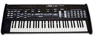
Well, it would be nice to chat with fellow owners of the son of
Chroma. If anyone feels the urge to answer a question or two, here's
one...on the inside of the polaris, there are 4 different philips
head pots...does anyone know what each of them is for? I'm assuming
that they may be for a master tuneing control, or filter
calibration...I'm just curious though, since I don't want to move one
if I don't need to.
Cheers,
Byron
time ago.
Well, it would be nice to chat with fellow owners of the son of
Chroma. If anyone feels the urge to answer a question or two, here's
one...on the inside of the polaris, there are 4 different philips
head pots...does anyone know what each of them is for? I'm assuming
that they may be for a master tuneing control, or filter
calibration...I'm just curious though, since I don't want to move one
if I don't need to.
Cheers,
Byron