Yahoo Groups archive

Homebrew PCBs

Index last updated: 2026-04-13 23:21 UTC

Thread

reducing mask image with lens

reducing mask image with lens

2017-02-19 by Jeff Heiss

The conventional method of using photoresist is to install a mask on top the
photoresist.  I'm considering using a two-to-one reducing lens and placing
the mask above the reducing lens.  Since the mask image would be reduced to
half size when it hits the copper clad, the fine detail requirements of the
mask and printer are reduced. For example a 5 mil trance on the PCB would be
printed as a 10 mil trace on the mask (printer transparency).  Is a reducing
lens possible?  Are there any tradeoffs with a reducing method?


A setup for a reducing lens -
http://archive.cnx.org/resources/fb001372e360c7bddb6939364bfb77a57420e7dd/5.
15.png

Attachments

RE: [Homebrew_PCBs] reducing mask image with lens [1 Attachment]

2017-02-19 by Andrew Volk

This sort of thing was done for a long time to make plates for fabricating
integrated circuits for quite a while. (ICs use a photosensitive resist spun
onto the wafers.)  Optics had to be precise to set the exact reduction and
be accurate across the field.  However, the area exposed was generally quite
small, less than 0.5 inches on a side.  The images were stepped and repeated
across the plate to the size of the wafer.  The exposures to make the wafers
were done with contact printing.  However, defects were created when the
plate touch the wafer causing bad die and yield loss.  Later a collimated
light beam as use through a plate to make non-contact printing.  Now instead
of full wafer exposure plates, the images are in a relative small plate
(reticle) with a few to several die in a cluster.  These images are made in
redundant groups with the most perfect (defect free) version is selected for
production use.  The cluster is projected and stepped across the wafer to in
consecutive exposures - a   bit slower, but better final yields.


The idea of doing a reduction, 2:1 or 10:1 as we did back in the day is
possible, but would require very good optics with a wide undistorted
projection field - bigger than your biggest board.  That would present a
challenge that grew exponentially with board size.
Show quoted textHide quoted text
From: Homebrew_PCBs@yahoogroups.com [mailto:Homebrew_PCBs@yahoogroups.com] 
Sent: Saturday, February 18, 2017 10:28 PM
To: Homebrew_PCBs@yahoogroups.com
Subject: [Homebrew_PCBs] reducing mask image with lens [1 Attachment]


The conventional method of using photoresist is to install a mask on top the
photoresist.  I'm considering using a two-to-one reducing lens and placing
the mask above the reducing lens.  Since the mask image would be reduced to
half size when it hits the copper clad, the fine detail requirements of the
mask and printer are reduced. For example a 5 mil trance on the PCB would be
printed as a 10 mil trace on the mask (printer transparency).  Is a reducing
lens possible?  Are there any tradeoffs with a reducing method?


A setup for a reducing lens -
http://archive.cnx.org/resources/fb001372e360c7bddb6939364bfb77a57420e7dd/5.
15.png

Re: [Homebrew_PCBs] reducing mask image with lens [1 Attachment]

2017-02-19 by Harvey Altstadter

Jeff,

In principle, this should work, but as usual, the devil is in the 
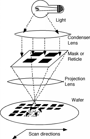
details. The most obvious to me is that you are limited to small boards with this set up. The glass has to be larger than your original, and it also has to have a flat field, so as not to introduce distortion. Large glass with good optical characteristic tends to be expensive. The glass will also have to be of a type that has a high transmission of UV if you are exposing photoresist. You will have to provide a mechanism to position the lamp/lens combination to optimize results, and also a mechanism for focusing the image on the board. Focus could also be an issue if going to photoresist. The focal point for UV light will be a bit different from white light because of the shorter wavelength. Somewhere in the setup, there has to be a structure to place the lens the right distance from the board to produce the exact magnification. This would be an awesome project...

I am not sure what problem this solves. The major problem with laser printing that I see is that the narrower the trace, the fewer dots there will be to generate the trace width. With a 600 dpi printer, a 10 mil trace that is aligned with the printer scan direction will have 6 dots. This is relatively reasonable. A 5 mil trace with 3 dots is not. Changing to a 1200 dpi printer solves that problem, but at expense.\ufffd Clearly, the transfer process is limited in trace size by the resolution of the printer. Printing on transparencies, and using them as photomasks with the photoresist process has the same limitation because we are still dealing with too few dots. To do this properly requires a high quality laser plotter to make the photo mask, or in direct write to the photoresist.

My $0.02
Harvey
Show quoted textHide quoted text
On 2/18/2017 11:27 PM, 'Jeff Heiss' jeff.heiss@... [Homebrew_PCBs] wrote:

A setup for a reducing lens - http://archive.cnx.org/resources/fb001372e360c7bddb6939364bfb77a57420e7dd/5.15.png


Re: [Homebrew_PCBs] reducing mask image with lens [1 Attachment]

2017-02-20 by jeff.heiss@...

This is very interesting info, thanks guys. Testing a current day HP laser printer at 600dpi and 1200dpi did not show appreciable resolution increase between 600 and 1200. Traces 5mil to 8mil were more gaussian in appearance instead of a desired sharp edge. I envisioned using 35mm film enlarger in reverse to reduce the mask size but it occurs to me that 35mm is the largest possible board size.

This guy experimented with a microscope for reduction. Not feasible for PCBs but neat. https://www.allaboutcircuits.com/projects/diy-pcb-photolithography-microfeature-fabrication/

Re: [Homebrew_PCBs] reducing mask image with lens

2017-02-21 by Donald H Locker

From my in-house darkroom experience many years ago, I discovered that the lens system required to image a flat plane to another flat plane (i.e. film to paper) was very different from the lens system required to image a 3-d scene to a flat plane (i.e. real world to film). Check out process camera lense systems.

Donald.

----- Original Message -----
Show quoted textHide quoted text
> From: "jeff.heiss@... [Homebrew_PCBs]" <Homebrew_PCBs@yahoogroups.com>
> To: "Homebrew PCBs" <Homebrew_PCBs@yahoogroups.com>
> Sent: Monday, February 20, 2017 2:46:58 PM
> Subject: Re: [Homebrew_PCBs] reducing mask image with lens
> 
> This is very interesting info, thanks guys.  Testing a current day HP laser
> printer at 600dpi and 1200dpi did not show appreciable resolution increase
> between 600 and 1200.  Traces 5mil to 8mil were more gaussian in appearance
> instead of a desired sharp edge.  I envisioned using 35mm film enlarger in
> reverse to reduce the mask size but it occurs to me that 35mm is the largest
> possible board size.
>  This guy experimented with a microscope for reduction.  Not feasible for
>  PCBs but neat.
>  https://www.allaboutcircuits.com/projects/diy-pcb-photolithography-microfeature-fabrication/
>

Move to quarantaine

This moves the raw source file on disk only. The archive index is not changed automatically, so you still need to run a manual refresh afterward.