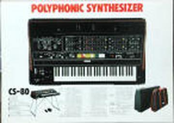
just as long as it steals allĀ released keys in sustainĀ II
Max...that is what matters most.
-----Original message-----
From: "Max Fazio"
faxiomas@...Date: Thu, 19 Feb 2009 04:51:44 -0700
To:
yamahacs80@yahoogroups.comSubject: Re: [yamahacs80] Voice allocation ?
I built a CS-KAS based on PICs a while ago. It works, but I did not
adopt their strange assign order and instead went with the two popular
ones, "steal oldest note" and "steal least used note". I need to
finish
that thing, it still needs the gliss/porta function to actually work.
Never enough time...
Scott
Doesn't the CS have, already embedded, a "steal the oldest" logic
which integrates with this weird pitch code encoding+LRU?
Basically, for what I could understand, in a Sustain-II state, if you
have all 8 voices playing and have a new note playing, the oldest
voice playing is stealed by the newnote
Yes, this is a common Yamaha trick, though nothing beats the -12V
logic of the GS1, with a -7V supply node for the 5-volt logic (the
patch
controller). Gotta love that old PMOS technology... ;)
I seemed to understand that the GS-1 assigner operates with a very
similar logic, compared to the original KAS, have you got any more
resources to share with us perhaps?
Cheerz
M
----- Original Message -----
From: The Old Crow
To: yamahacs80@yahoogroups.com
Sent: Thursday, February 19, 2009 5:53 AM
Subject: Re: [yamahacs80] Voice allocation ?
Colin f wrote:
>
>
>> They use the same
>> ring memory table in the GX-1 and key assigner of the CS 50/60/80.
>> There is a somewhat cryptic explanation in the CS service
>> guide, pages
>> 11 to 19, describing the encoder for 4 voices. JH references the
>> service guide on his CS50 page,
>>
>
> You'll find the GX1 KAS schematic here:
> http://www.sequentix.com/gx1/GX1-KAS.zip
>
> Are the separate assigner and octave chips used elsewhere ?
> Looks like they were combined into a single chip for the CS synths,
with a
> matrix of keys rather than an input for every single key.
>
They integrated the octave and semitone into a sort of matrix; it
would first sense the octaves of keys by setting the octave pins to 0V
(a grey bit, not logic 1 or 0) and setting the note pins to logic "1"
aka -6.5v. IT would record the octaves found in a buffer. Then it
would ∗reverse∗ the sense of a key and set all the 1s (-6.5v) to 0s
(+8.5v). This would show which actual notes in each octave were
active. Then they pack up the 3-bit octave code and 4-bit note code
for
good old time-division multiplexing at the DAC.Skew the clock, and you
get the glissando/portamento. What a weird encoder. :)
I built a CS-KAS based on PICs a while ago. It works, but I did not
adopt their strange assign order and instead went with the two popular
ones, "steal oldest note" and "steal least used note". I need to
finish
that thing, it still needs the gliss/porta function to actually work.
Never enough time...
>> If you look closely you'll see the actual electrical
>> operation of the
>> key scanner is ternary, not binary, it uses both -6.5v to 0 and 0
to
>> +8.5v to derive logic states.
>>
>
> I'm sure that's not the case on the GX.
> It has a +6/-9v supply for the assigner and octave scanning chips,
but that is just to limit the total supply voltage to 15v for the CMOS
devices that are used for the de-mux etc.
>
>
Yes, this is a common Yamaha trick,though nothing beats the -12V
logic of the GS1, with a -7V supply node for the 5-volt logic (the
patch
controller). Gotta love that old PMOS technology... ;)
Crow
/∗∗/
[Non-text portions of this message have been removed]
[Non-text portions of this message have been removed]